LED Polarity Identification
How to test and determine polarity for LEDS
All LEDS have a polarity to them. If you hook them up backwards, they won't light. If you are remote mounting your LEDS is important to solder color coded wires onto the LED so that you can identify the polarity of the LED when you attach the wires to the printed circuit board. I like to use black for the negative lead and another color for the positive lead. If the wires need to blend in with something, I tend to use black for negative and brown for positive. If the wires won't be seen, I use black for negative and red for positive.
In order to identify which lead is positive and which lead is negative there are three common methods.
Method 1: Visual indications
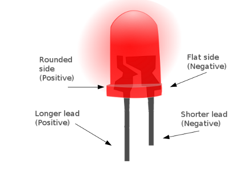
The first method is to examine the LED itself. Most LEDS will mark the negative lead in two ways. First, the negative lead is the shorter of the two leads. Secondly on the LED body itself, there is usually a flat side at the bottom of the LED next to the negative lead. The bottom of the LED next to the positive lead is usually curved. This is useful if you cut the leads off shorter first and then forget which lead was the shorter one.

Method 2: Multi-meter testing
The second method is to use a multi-meter on the diode setting to test which way the LED conducts.
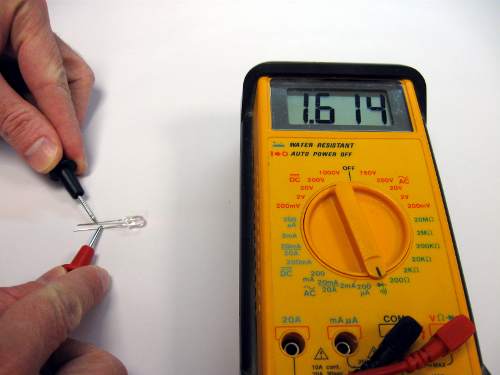
First set your multi-meter to the diode setting. Next, touch one lead on the multi-meter to one lead on the LED and the other lead on the multi-meter to the other LED lead. If you have the correct polarity, the multi-meter should show a number on the display. Some multi-meters will also cause the LED to glow dimly.

In the above image, the red lead of the multi-meter is on the positive LED lead and the black multi-meter lead is on the negative LED lead. It's hard to tell from the picture, but the LED is dimly glowing red.
By the way, the number on the multi-meter display is the forward voltage of the LED. Different color LEDS can have different forward voltages.
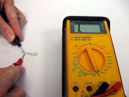
If you have the LED attached backwards, the voltmeter will read either "---" or "1" indicating no conduction. In the photo below, the LED is reverse polarity. Notice how the LED does not glow.

The multi-meter method is great for both determining the polarity of the LED and also testing that it is not dead! If the LED does not conduct in either direction, it is possible that the LED is burned out or defective. Not all multi-meters will have enough current to light the LED. Don't worry if the multi-meter shows a number on the display but the LED does not appear to light. The multi-meter provides a very low current in this setting, so it may not be enough current for the LED to glow.
Method 3: Test setup with 9V battery
The final method to both test the LED and determine polarity is to use a 9V battery, a 1K ohm resistor and the LED. This method will light the led when the polarity is correct, and also allow you to verify the color of the LED.
WARNING
Never connect the LED directly to a source of power without a resistor in series. Directly connecting the LED to power, even a small battery source, will burn out the LED instantly. It may also get very hot very quickly in the process.
Always connect the proper value dropping resistor in series with the LED. If in doubt, use a high value resistor like 1K ohm or higher at first.
NEVER connect LEDS to AC power even with a dropping resistor. LEDS should only be connected to a DC source with a dropping resistor.
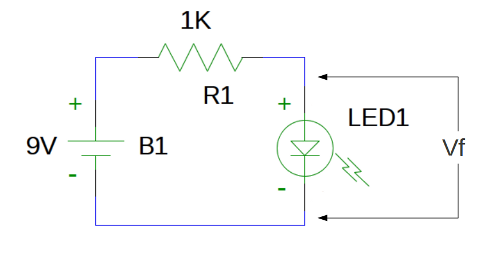
Connect the positive on the 9V battery to one end of the 1K resistor. Connect the other end of the 1K resistor to one lead of the LED and the other lead of the LED to the negative on the 9V battery. If the LED does not light, reverse the connections of the LED. See the schematic below:

Once you have the LED lit, the lead connected to the negative of the 9V battery is the negative LED lead, the other lead is the positive. If your LED does not light in either direction, check your circuit connections and that you have a good 9V battery. If the LED still does not light, chances are it is defective.
The 1K resistor value and 9V battery is safe for most LEDS as it only allows a few milliamps of current to flow. The LED will not light at full brightness, but it will light enough for you to see that it is working and what color it is.
Once you have the LED lit, you can use a voltmeter to measure the voltage drop across the LED to determine the LED forward voltage drop, shown as Vf on the schematic. You can then use this value in your calculations to determine what resistor you need to use in your final application circuit. Vf varies depending on the LED color. It should measure somewhere between about 1.7V and 3.5V.
