
OwlCircuits
Personal Weather Station
A weather station based on the Raspberry Pi
6. Adding the first remote sensor
Now that we have a wireless link between our remote sensor module and the Raspberry Pi, which will act as our base station, it is time to start adding actual sensors. We will also build up the complete infrastructure of receiving the sensor data, processing it, and displaying it on our internal web page at this stage. We want to keep in mind that as we build up our infrastructure using the first sensor we want to make it easy to add additional sensors to our weather station at a later date.
We will need three major components for our first sensor:
- The microcontroller program that reads the sensor and transmits the data back to the base station
- The Perl script that runs in the background on the Raspberry Pi that will receive the sensor data and write it to a log file.
- The Perl script that runs as a cron job on the Raspberry Pi which will process the log file and generate the web page files.
6.1 Temperature and Humidity
The first remote sensor that we will add is outdoor temperature and humidity. It's actually two sensors contained in the same package. The Honeywell HIH-6131 humidity and temperature sensor gives us both relative humidity and temperature from the same sensor. It has an I2C interface which will easily interface to our microcontroller.
6.2 A closer look at the HIH6131 sensor
The HIH6131 is in a tiny package so it's best to get one that is mounted on a breakout board. The HIH6130 shown in figure 6.1 is mounted on a breakout board from Spark Fun electronics.
The only difference between the HIH6130 and the HIH6131 is that the 6131 version has a hydrophobic filter while the 6130 does not. The hydrophobic filter is used in environments that may have 100% humidity for extended periods of time. This filter allows the sensor to dry out more quickly in condensing environments allowing a quicker sensor response time. In our weather station application, it does not matter which sensor , the 6130 or the 6131 we use as they both perform electrically and functionally the same.
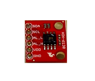
Figure 6.1: HIH6131 Temperature and Humidity sensor
To access the data in the sensor, we use the I2C bus. I2C is a serial protocol that only uses two pins on the microcontroller, SCL and SDL. SCL is the serial clock line and SDL is the the serial data line. You can implement this protocol in software in the microcontroller, but it is much easier to select a microcontroller that contains a built in I2C module in hardware. Having a built in I2C module in the microcontroller means you only need to do simple register reads and writes to access the sensor.
The HIH6131 sensor requires an I2C register write in order to initiate a measurement . The sensor's 6 bit address is hard coded by the manufacturer to 0x27 and the lowest bit determines if you are reading or writing to the sensor. A 0 in the lowest bit indicates a write to the sensor and a 1 in the lowest bit indicates a read as shown in figure 6.2. Therefore, to write to the sensor we would send a 0x4E over the I2C bus, and to read we would send a 0x4F. We need to send a 0x4E over the I2C bus to initiate a sensor measurement cycle first .
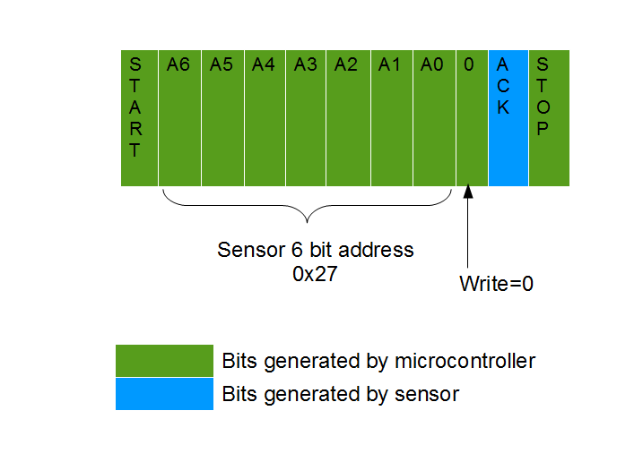
Figure 6.2: I2C register write to initiate a sensor measurement
According to the HIH6131 data sheet, a measurement takes at most 37ms to complete. If we attempt to read the humidity and temperature values before the measurement is complete, we will get an error condition along with stale data. To compensate for this , we will delay about 100ms between requesting a measurement and reading of the humidity and temperature data.
To read the humidity and temperature data we initiate an I2C register read to the sensor address of 0x27. Therefore, we need to send a 0x4F over the I2C bus to indicate to the sensor we want to read the humidity and temperature result.
The HIH6131 sensor responds with 4 bytes of data. The first two bytes are the humidity value and the second two bytes are the temperature data. The humidity data is composed of only 14 bits and the upper 2 bits of the 16bit data is the status of the sensor. For the temperature data, the upper 14 bits of the 16 bit temperature data is the temperature value, and the lower 2 bits are don't cares. The complete read transaction for the HIH6131 sensor is shown in figure 6.3.
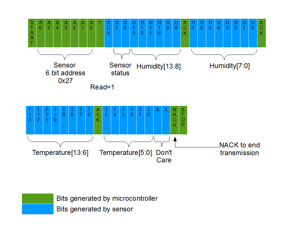
Figure 6.3: I2C register read of humidity and temperature result
The humidity and temperature data returned are the raw sensor readings. In order to display the humidity as relative humidity between 0% and 100%, and temperature in degrees Celsius, we need to be aware of the equations that convert the raw sensor readings to actual humidity and temperature readings. We will send the raw readings back to the Raspberry Pi to be converted and logged. There is no reason to spend computational power to convert the values in the battery powered microcontroller when we have plenty of processing power on the Raspberry Pi. From the HIH6131 data sheet, the relative humidity is computed as show in equation 6.1 and temperature in degrees Celsius is computed as shown in equation 6.2.
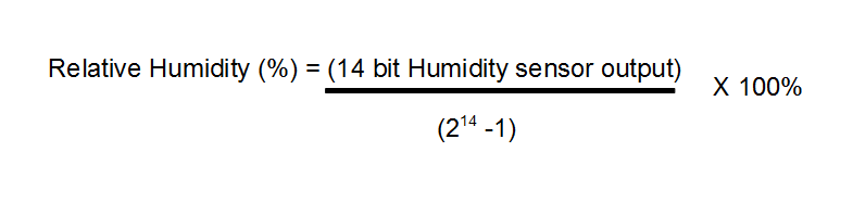
Equation 6.1: Relative Humidity equation for HIH6131 sensor
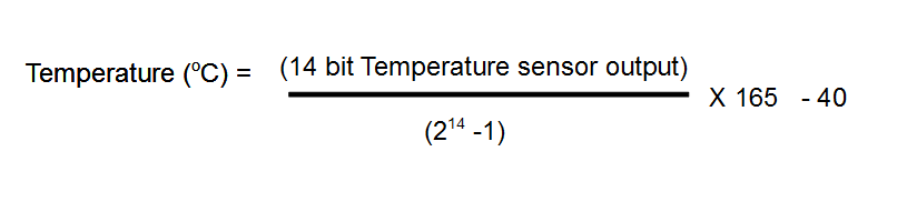
Equation 6.2 Temperature in degrees Celsius equation for HIH6131 sensor
6.3 Temperature & Humidity remote sensor hardware
Now we will build the hardware for our first remote sensor. The hardware will be very similar to our wireless link test hardware found in section 5.2. We will need to add the HIH6131 sensor to the microcontroller and XBee setup. The schematic for our temperature and humidity remote sensor is shown in figure 6.4.
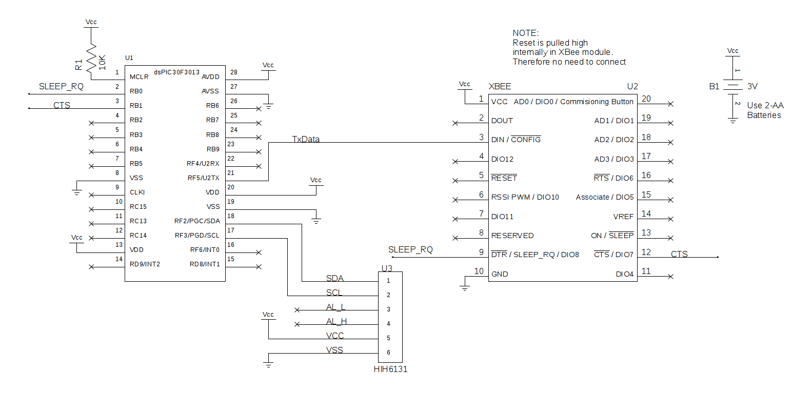
Figure 6.4: Schematic of HIH6131 remote sensor unit
It is highly recommended to first build and test the circuit on a breadboard as shown in figure 6.5. Building the circuit on a breadboard allows you to test and debug the circuit easily. If a change to the wiring needs to be made, it is much easier to change it on a breadboard rather than a soldered PCB.
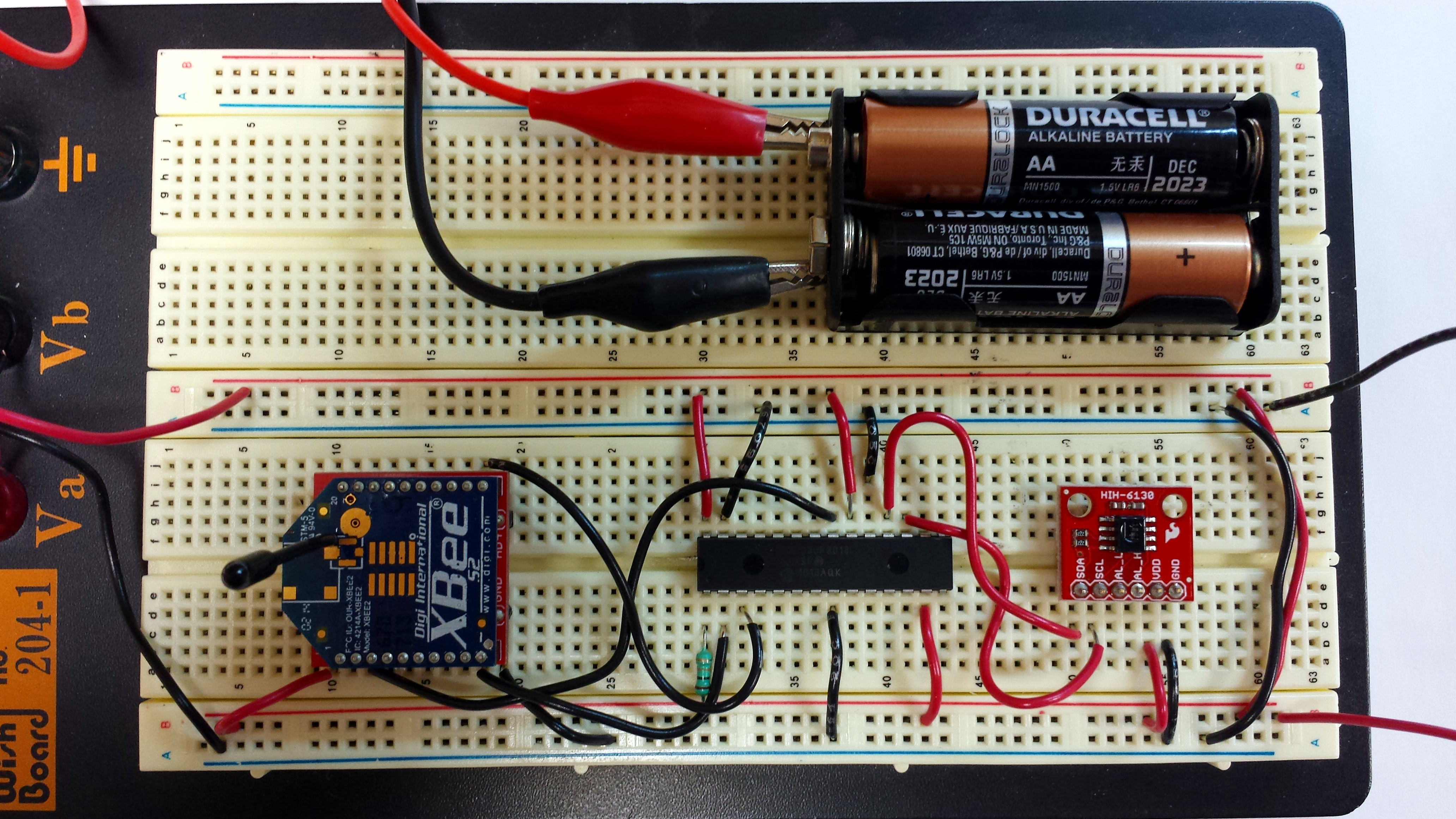
Figure 6.5: HIH6131 remote sensor test circuit on breadboard
The microcontroller used is a dsPIC30F3013. This is a 28 pin microcontroller made by Microchip. You can substitute a different microcontroller but you would need to adapt the program to work with the different microcontroller. Make sure that whatever microcontroller you use is capable of running off of 3VDC as we will be running the sensor unit off of 2 AA batteries.
The dsPIC30F3013 has a built in UART module and a built in I2C module. These two modules will make programming simpler since both the I2C and UART protocols will be handled directly by the microcontroller's hardware modules.
One issue with using the dsPIC30F3013 is that the I2C pins are multiplexed with the PIC's programming pins. This means that we need to program the microcontroller separately before plugging it in to our circuit. This drawback makes debugging tedious as if we wanted to debug something, we would have to keep swapping the microcontroller in and out of the circuit to reprogram it. A simpler solution would be to use a larger pin count, but similar architecture microcontroller for debugging and development, and once everything is working, re-compile the working program for the smaller microcontroller. The dsPIC30F4013 is a similar microcontroller to the dsPIC30F3013 except the 4013 comes in a larger 40 pin package. The 4013, also has the programming pins and the I2C pins on different physical pins, allowing us to program and debug the remote sensor unit microcontroller without having to remove the microcontroller from the circuit to program it.
Once the remote sensor unit has been confirmed working on the breadboard, it can then be moved to a prototype perf-board as shown in figure 6.6. Make sure to socket all parts so that it is easy to change out a part. It is also important to make sure that you build the circuit on a PCB small enough to fit in the enclosure that will protect the unit from the elements. A suitable enclosure is a plastic outdoor rated PVC electrical box which is described in detail in section 6.6.
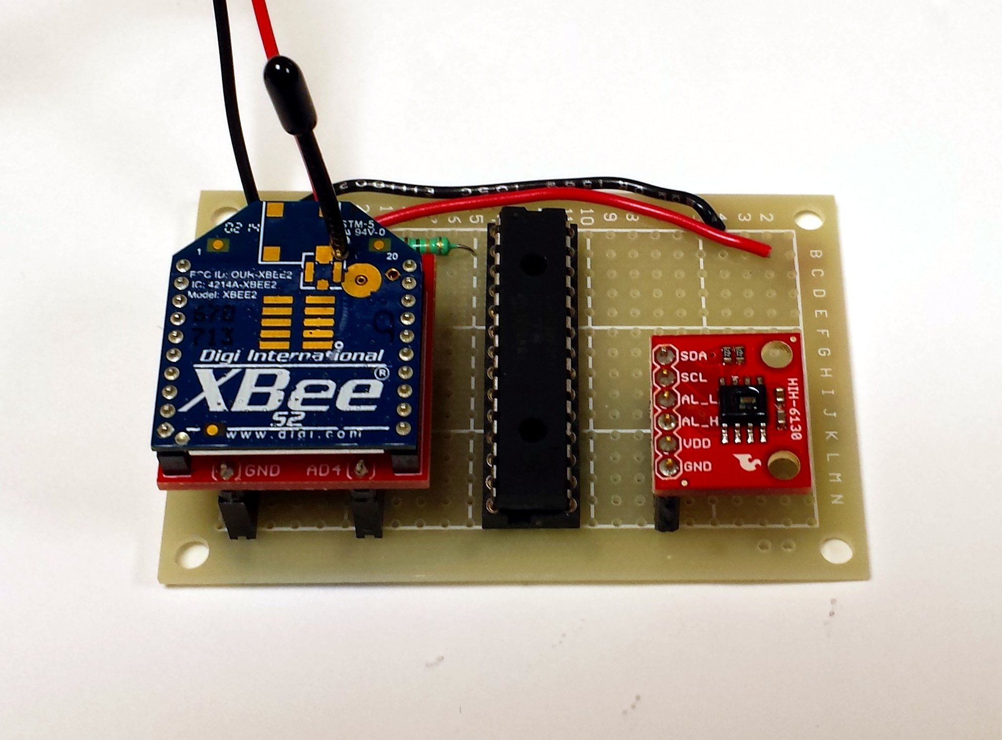
Figure 6.6: HIH6130 remote sensor built on a small PCB
For the time being, it's best to continue to test the circuit on the breadboard until we have verified that we can receive the temperature and humidity data on the Raspberry Pi successfully. The following sections will build up our initial infrastructure for receiving and logging remote sensor data using the HIH6131 temperature and humidity sensor as an example. Adding additional sensors will be easier once we have the first sensor and its related infrastructure completed.


