
OwlCircuits
Personal Weather Station
A weather station based on the Raspberry Pi
3.2 ZigBee, XBee and mesh networking
We have seen how using a simple wireless transmitter results in a lot more work and software overhead to ensure reliable data transmission. However we can use a radio module that takes care of all the error detection and correction for us. The most popular low power digital radio system is based on the ZigBee protocol.
ZigBee is a standard protocol for implementing mesh networks. XBee is a brand name of digital radios that use the ZigBee protocol.
A mesh network is a network where devices are connected together in a topology where devices are not necessarily connected directly to the master of the network. A device can be connected to another device which is then connected to the master of the network. Devices communicate by passing data from one device to another. Some devices act as an intermediary where they will relay a message from one device to another device that is not within range of the first device. Figure 3.5 shows an example of a simple mesh network.
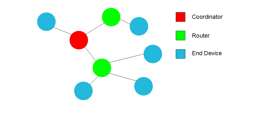
Figure 3.5: A simple mesh network
3.2.1 Coordinators, routers and end devices
There are three types of devices in a typical ZigBee network; coordinators, routers and end devices. With XBee devices, the physical hardware is the same for all three types. The firmware that you program into each device is what determines if the device is acting as a coordinator, router or end device.
For every network established, there is only one coordinator device. The coordinator is considered the master of the network. It is responsible for creating the network, picking the operating channel and assigning addresses to devices joining the network. A coordinator must always be powered.
A router is a device that can talk to a microcontroller and send data back to the coordinator. However, a router can also pass data from other devices back to the coordinator. This is useful if a device is out of range of the coordinator. As long as a device can reach a nearby router, its data can be passed back to the coordinator as shown in figure 3.6. Since a router needs to be able to pass data back to the coordinator from other devices, the router needs to be powered continuously.
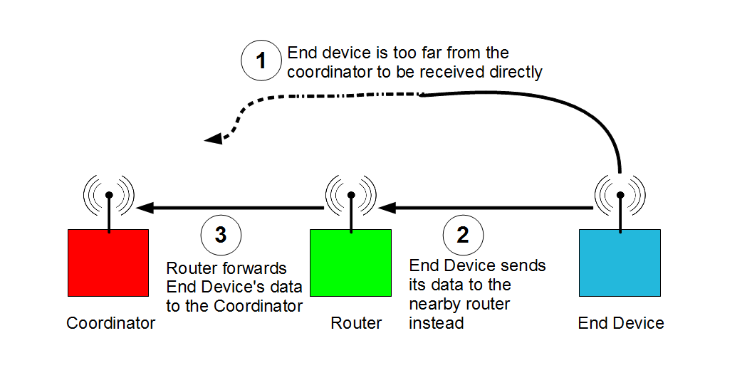
Figure 3.6: A XBee router forwarding data from an out of range device
An end device is similar to a router except an end device can't relay messages from other devices back to the coordinator. An end device can be put into a low power sleep mode to conserve power. End devices are designed for battery powered applications where they only periodically power up and send data to the coordinator. End devices can talk directly to a coordinator, or they can talk to a router which will pass the end device's data back to the coordinator.
3.2.2 Channels and addressing
The 2.4GHz ISM (Industrial Scientific Medical) frequency band is quite crowded with devices. Many consumer devices use the 2.4GHz band, everything from wireless routers, cordless phones and garage door openers. In order for the ZigBee network to work reliably in the 2.4GHz band it needs to first select an operating channel.
The 2.4GHz band is actually a range of frequencies around 2.4GHz. It is divided in 16 channels that range from 2.405Ghz to 2.480GHz in 5MHz steps. A ZigBee coordinator will perform an energy scan on each of the channels and choose a channel that appears to be not in use by other 2.4GHz devices. In order for two ZigBee devices they need to be on the same operating channel.
Once the coordinator selects an operating channel, it will then pick a Personal Area Network (PAN) ID. This ID is the network identification that all devices on the network will share. This allows multiple independent ZigBee networks to exist. Compared to a home WiFi network, this would be similar to the network name that you see when you connect to your home network.
Within the same operating channel and PAN ID, devices communicate with each other using either a 16 bit address which is assigned by the coordinator, or the device's 64 bit unique serial number. The coordinator is always located at address zero.
Note that for one device to communicate with another, they both need to be part of the same network. This means that each device needs to be on the same operating channel, and have the same PAN ID. Once they are part of the same network the two devices can send data to each other provided they know each others address. This can be either the device's unique serial number or the 16 bit address assigned to the device by the coordinator when it initially joined the network.
Figure 3.7 shows multiple independent networks operating within range of each other. Note that only devices with connecting lines in the figure are able to communicate with each other since they are part of the same network.
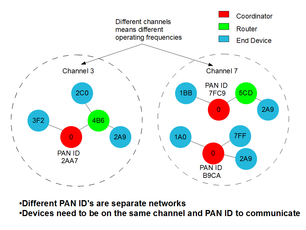
Figure 3.7: XBee device networks and addressing
3.2.3 Configuring devices
XBee devices need to be configured much like a microcontroller needs to be programmed in order for it to do something useful.
A XBee device needs to be programmed with the correct firmware depending on what type of device you want it to be; coordinator, router or end device. The hardware is exactly the same for all three types of devices, their behaviour is determined by the firmware loaded.
There is also various configuration settings that need to be programmed into each device. Settings that control the selection of operating channels, PAN ID, and destination addresses all need to be programmed into a device before it can properly operate on a ZigBee network.
XBee devices are programmed using commands sent through their UART port. You connect the XBee device through its UART to a host computer using a programming adapter. The programming adapter is simply a USB to UART bridge chip. The most common USB to UART bridge chip is made by the company FTDI. Most programming adapters use this FTDI USB to UART converter chip.
One important note is that the XBee's UART can only operate at 3.3V. You can't directly connect the XBee UART to a computer as the computer's UART usually operates at +/-12V. Directly connecting the XBee UART to a computer serial port can permanently damage the XBee module. It is worth investing in a programming adapter for the XBee since the programming adapter will take care of providing the correct voltage to the XBee module. Most programming adapters are USB on the host side, so it makes it easy to connect to modern computers.
Once you have a programming adapter connected to the computer, you can send the commands to program the XBee directly to the XBee module by typing the commands in a serial port program like hyper-terminal. This requires issuing each command manually to configure each device.
A simpler method is to install the free program XCTU from the manufacturer of XBee. XCTU allows you to use a graphical interface to download firmware and change settings in the XBee modules.
3.2.4 Sending data
The simplest method for sending data through a XBee network is to use transparent mode. Transparent mode is also called AT mode. In transparent mode any data you send into the transmitting XBee's UART will come out on the receiving XBee's UART. The receiving XBee's address is pre-programmed into the transmitting XBee's configuration.
Transparent AT mode works fine for simple networks with very few XBee devices on the network. The problem with AT mode is since the destination address is pre-programmed into the transmitting XBee's configuration, sending to a different XBee receiver on the same network requires re-programming the transmitting XBee's configuration to reflect the new destination address.
A XBee network with multiple devices can use API mode. API mode requires the transmitted data to be wrapped with a packet before sending it into the UART of the XBee. The advantage to using API mode packets is that the destination address for the data is part of the packet. This allows us to easily send data to different devices on the network by simply addressing the correct destination device within the data packet. There is no need to re-program a transmitting device when we want to talk to a different receiving device. All of the data required to communicate with any device on the network is contained within the API data packet.


