
OwlCircuits
LED Airport Beacon Lights Circuit
Pre-programmed microcontoller for controlling LED special effects
This microcontroller is used to simulate airport, water or transmission tower beacon lights. It is used to drive LEDS only.
This circuit has 4 configureable modes that allow you to select the type of beacon light you want to use. It can simulate fast strobes on modern towers as well as old style incandescent beacons that slowly fade in and out. You can use any color of LEDS that you want. See the section below for a more detailed description of the operating modes.
The microcontroller comes pre-programmed so you don't need any special programmer or progamming experience to build this circuit. Basic soldering skills and components are all that is needed. The microcontroller is in a easy to solder 14 pin DIP package.
PINOUT
| Pin Name | Description |
|---|---|
| VDD | +3V to +5V DC supply |
| MODESEL1 | Mode selection pin for configuring operation |
| MODESEL0 | Mode selection pin for configuring operation |
| RESETb | Active low reset |
| BEACON0 to BEACON3 | 4 LED outputs for the beacon lights |
| NC | No Connection. Leave unconnected |
| VSS | Ground |
Application notes:
Power supply
The microcontroller runs off 3V to 5V DC only. Using other voltages will destroy the microcontroller. For use with LEDS only. Make sure to provide the proper series resistors for the LEDS to limit the current to less than 20mA each.
You can run this microcontroller circuit off of 2 AA type batteries in series to get 3V operation. However, the preferred method is to run on 5V operation using a voltage regulator , for example the LM7805. Connect the VDD pin to 3-5V DC and the VSS pin to ground. A 0.1uF bypass capacitor is recommended to be placed across the power supply pins to minimize electrical noise.
Reset
The RESETb pin is active low. This means that when you connect RESETb to 0V or ground , the device will not operate and all the outputs will be off. For normal operation, RESETb should be connected to the same VDD voltage supply through a 10K ohm 1/4 watt resistor.
Mode Selection
This microcontroller has two mode selection pins that allow you to select different modes of operation by simply connecting the MODESEL pins to either power or ground. This allows you to chose different operating modes without having to use a computer or programmer.
Pulling the MODESEL pin to VDD (power) creates a logic 1. Connecting the MODESEL pin to VSS (ground) creates a logic 0.
The following shows the different operating modes depending if you connect the appropriate MODESEL pin to VDD (power) or VSS(ground).
Fast strobe looks like the strobe lights on modern transmission towers.
Double flash is a slower two burst flash that makes it look more like a modern LED light source on a tower.
Incandescent mode has a slower dimming and brightning effect. This effect looks like older warning lights on water towers and buildings. It looks very much like a large incandescent light bulb that takes time to brighten and dim. Great for layouts that have older town scenes.
Incandescent offset mode is the same as incandescent mode however each LED brightens and dims slightly delayed from the others. This is usefull if you want each tower light to appear to be blinking independently of the others.
| MODESEL1 | MODESEL0 | Operating mode |
|---|---|---|
| VSS (0) | VSS (0) | Fast strobe |
| VSS (0) | VDD (1) | Double flash |
| VDD (1) | VSS (0) | Incandescent offset | VDD (1) | VDD (1) | Incandescent synchronized |
Outputs
The 4 LED outputs will drive the VDD supply to the LEDS. If you connect VDD to +3V DC , the outputs will drive 3V to the LEDS. If you connect VDD to 5V the outputs will drive 5V to the LEDS.
It is important to select a series resistor for each LED such that the maximum current is limited to less than 20mA. The micorcontroller can handle 20mA per output with a maximum total output of 200mA.
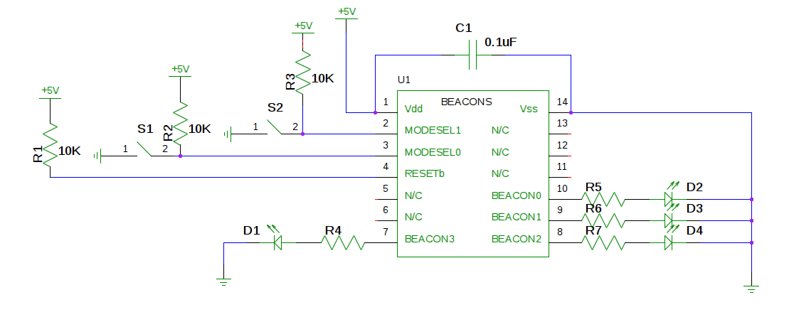
Example circuits
Below is an example circuit showing the typical way to hook up the microcontroller and LEDS. If you choose to remote mount the LEDS, use 22-24ga wire.
C1 is a bypass capacitor that helps to filter out electrical noise in the power going to the microcontroller.
By pulling the MODESEL pins up to VDD via a 10K ohm resistor, you will put a default value of VDD on the MODESEL pin. If you close the switch , it will pull the MODESEL pin to ground (VSS), selecting a different operating mode.
NOTE: The MODESEL pins are only read once when the device first gets power. Switching the value on the MODESEL pins during operation will have no effect. You need to power cycle or reset the microcontroller to select the new mode.
D1 to D4 are the LED outputs. Only use LEDS with this circuit. R4 to R7 should be selected to limit the current in the LEDS to less than 20mA. Note that different color LEDS will have different forward voltages , so R4 to R7 will most likely be different values when using different colored LEDS.
Click for a larger circuit diagram image.
| SW2 | SW1 | Operating mode |
|---|---|---|
| Closed (0) | Closed (0) | Fast strobe |
| Closed (0) | Open (1) | Double flash |
| Open (1) | Closed (0) | Incandescent offset |
| Open (1) | Open (1) | Incandescent synchronized |