
OwlCircuits
Personal Weather Station
A weather station based on the Raspberry Pi
6.6 Remote sensor enclosure
Now that we have the HIH6131 sensor transmitting the humidity and temperature back to the base station, we need to put it in a weatherproof enclosure so that we can safely mount it outside. If you have built the sensor hardware on a breadboard such as in figure 6.5, you will need to build it on a small two inch square prototype board similar to the one in figure 6.6.
Our enclosure needs to prevent rain and snow from getting on the electronics, but it can't be completely air tight as the humidity sensor needs access to the outside air. We could use a small project box, but past experience shows that these tend to crack and become brittle after being exposed to the weather for an extended period of time. A better choice is to use a outdoor rated PVC electrical box.
The box shown in figure 6.12 is a marine grade PVC electrical box. I'm not sure what the original purpose of this box is as there is absolutely no holes in the box at all. I'm guessing that you would drill holes and mount weatherproof connectors on the box to get electrical wires into it. The lid has a rubber gasket around it, and there are mounting feet on the bottom of the box. This PVC electrical box was about $10 at the local home improvement store.
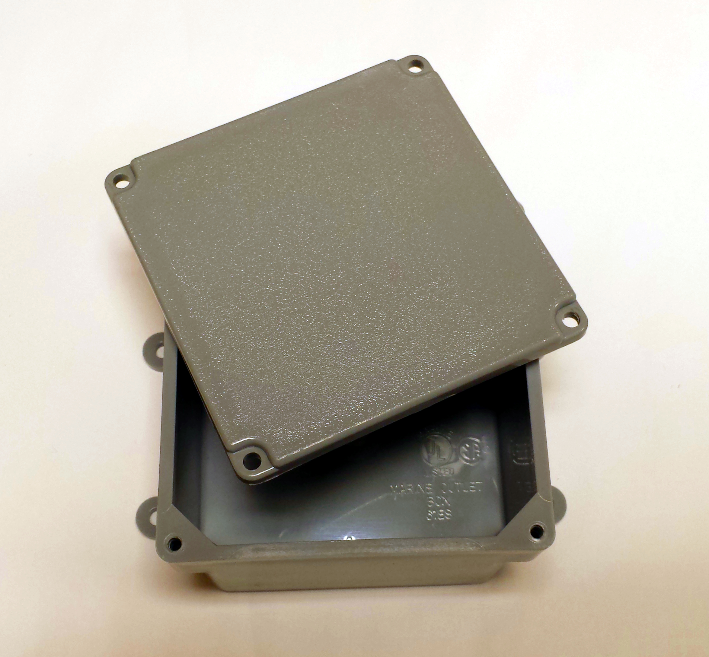
Figure 6.12: Marine grade PVC electrical box
We will make a few modifications to the electrical box to accommodate our sensor unit. First we need to make some mounting holes for the sensor unit PCB. The easiest way to do this is to turn the electrical box upside down and mark on the bottom of the electrical box the location for the PCB mounting holes. You should hold the completed PCB against the back of the electrical box and use a fine tip marker to mark where the mounting holes need to go. Make sure to leave room for the battery pack inside the box. I kept the sensor board to one side of the box, reserving the other side of the box for the battery pack. Use a 3/32 inch drill bit and drill the holes from the outside of the box on the bottom.
Once the mounting holes for the PCB have been drilled, it's a good idea to drill a couple of extra holes in the bottom of the box for drainage. In the event that water does somehow get inside the box, we want a way for it to get out.
Next we need to add some holes in the side of the box to let air in for the humidity sensor. We need the humidity sensor to have access to the outside air, but we still want the holes to be small to prevent rain and bugs from getting into the box. I used the same 3/32 inch drill bit and drilled three holes in each side of the PVC electrical box as show in figure 6.13.
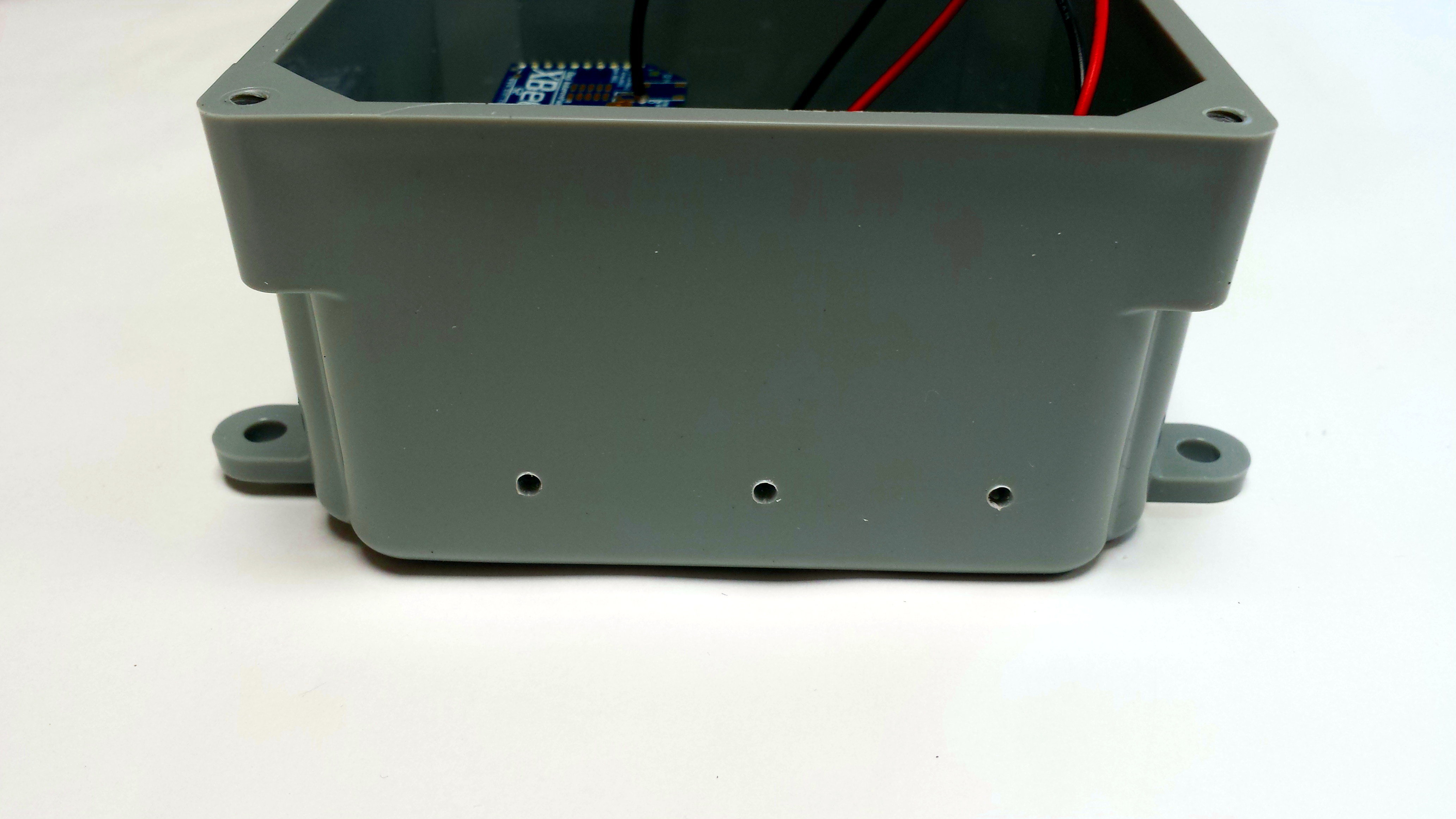
Figure 6.13: Vent holes for the humidity sensor
Finally we can mount the PCB inside the electrical box using 4-40 screws and nuts as shown in figure 6.14. Make sure to space the PCB off of the bottom of the box slightly. The easiest way to do this is to put a couple of 4-40 nuts on the 4-40 screw before you mount the PCB on the screws. The completed assembly is shown in figure 6.15.
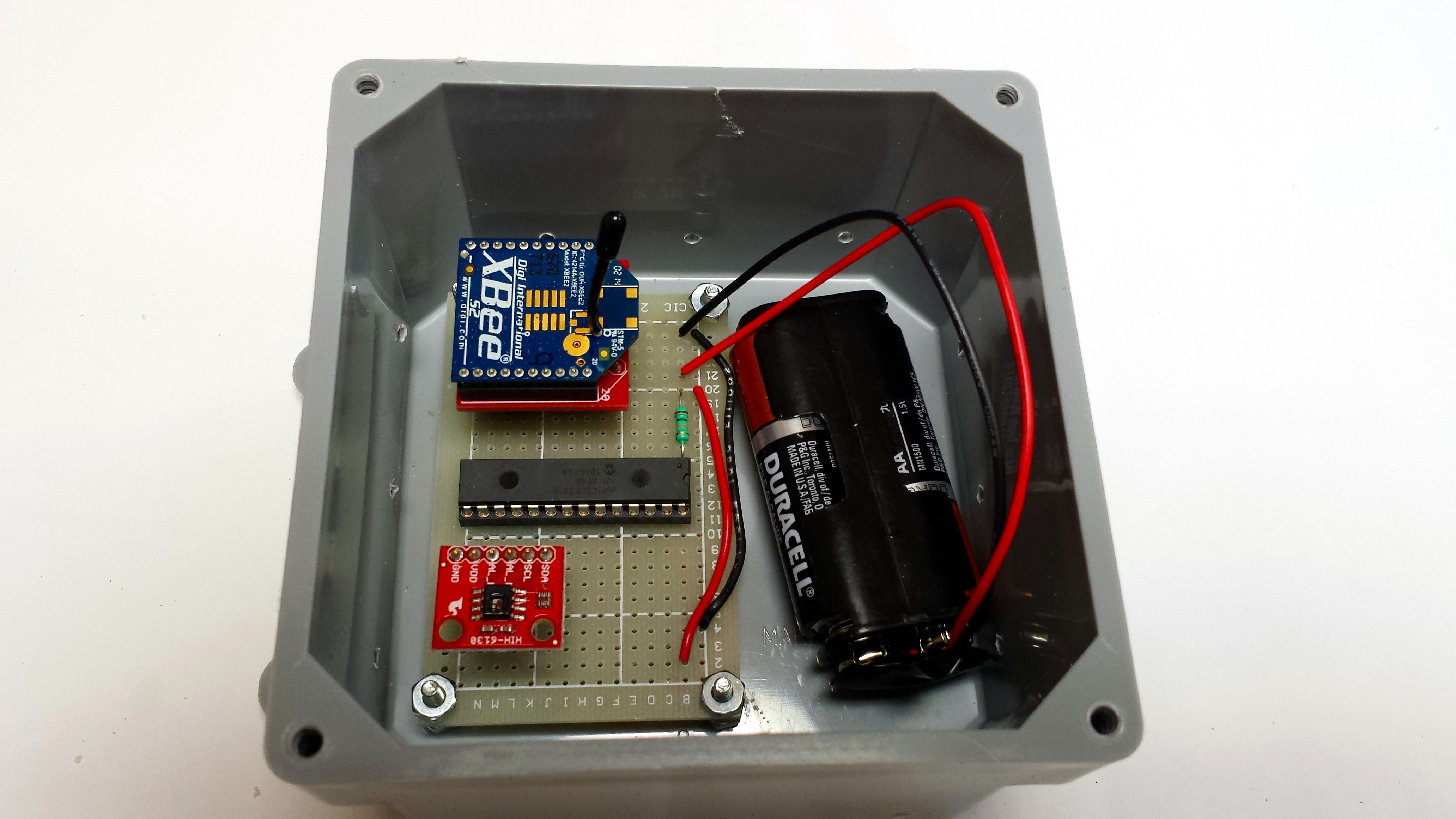
Figure 6.14: PCB mounted in enclosure
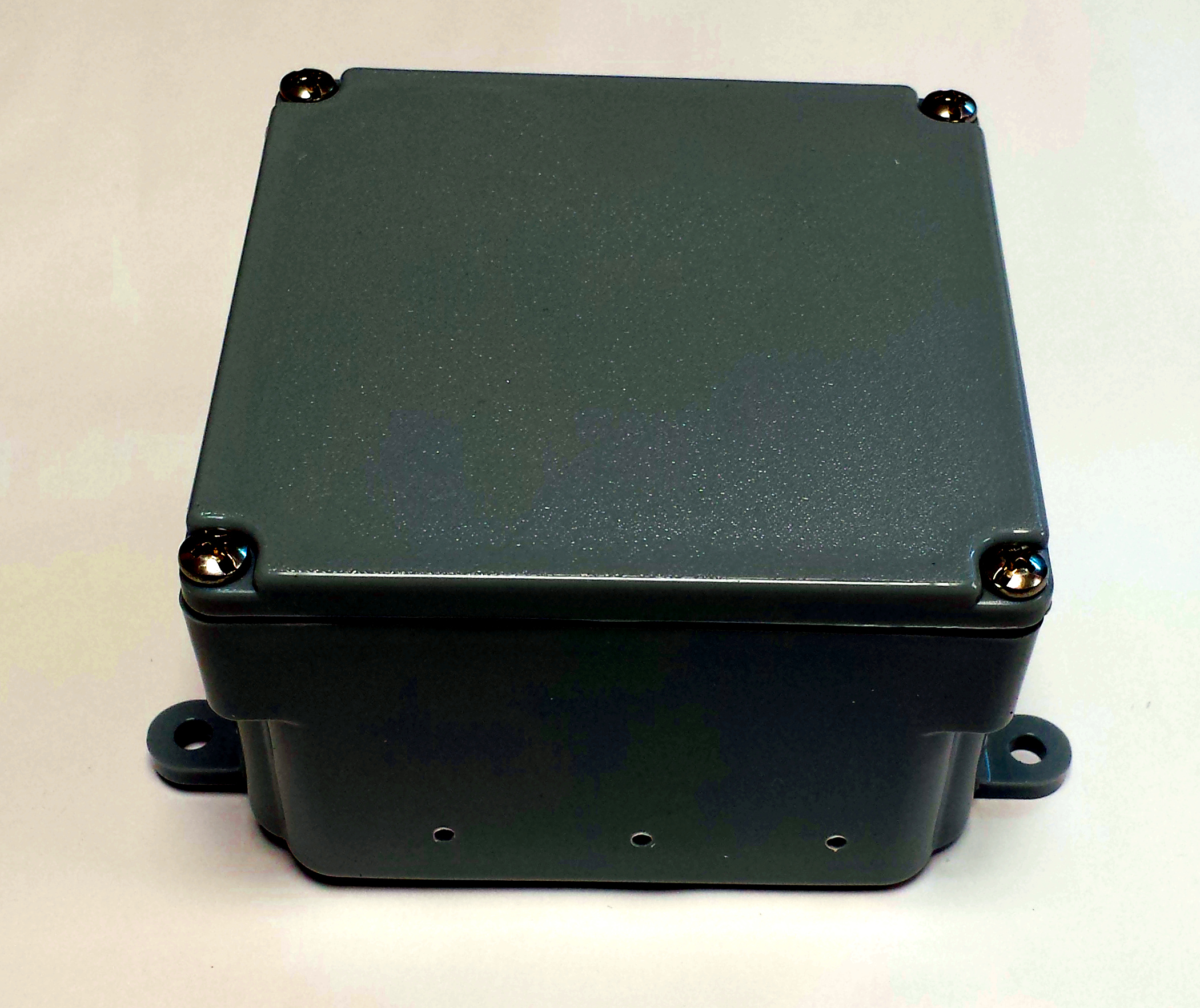
Figure 6.15: Completed HIH6131 sensor enclosure
6.7 Mounting the remote sensor
...


